PathTracer: Global Illumination
This is a university course project that I took in University at Buffalo on Computer Graphics.
I developed a simple path tracer that can render scenes with global illumination. The first two tasks focus on providing an efficient implementation of ray-scene geometry. In the third task (Pathtracer) I developed the ability to simulate how light bounces around the scene. Specifically, indirect and direct illumination. The pathtracer renders COLLADA files.
- Task 1. Generating Camera Rays
- Task 2. Handling ray-triangle and ray-sphere intersections;
- Task 3: Path tracing
Task 1. Generating Camera Rays
Steps:
- By default, rays are generated from the left bottom of a pixel. Sample a random number from 0 to 1 to add to the pixel coordinates. Normalise with respect to the screen coordinates. Subtract 0.5 from both x and y coordinates to center the pixel.
- Generate ray to this new normalised location with the camera position as the origin of the ray. Calculate the sensor height and sensor width using the vertical field of view of the camera and using trigonometry. Take care to handle units carefully as field of view will be returned in degrees, whereas the trig functions take angles in radians.
- Scale the normalised screen coordinates with the sensor width and sensor height calculated from step 2.
- The ray created is generated with respect to the camera space. This ray needs to be converted back to world space by multiplying the ray direction with the camera to world transformation matrix (given in camera).
Task 2. Handling ray-triangle and ray-sphere intersections
Ray-Triangle Intersection: I used the Moller-Trumbore algorithm for Ray-triangle intersection.
Steps:
- Scotty3D function of ray-triangle intersection returns a Trace structure which contains the information around the point where the ray hit the triangle. This contains the information of the ray that hits that object, if the hit happens and the position where the hit happens. It also modifies the max valid bound of the ray, so that other later hits (such as hits that are behind the object) are ignored.
- The figure illustrates equations to calculate the ray-triangle intersection. Solving the equations we get a vector of 3-dimensions. The first two coordinates (u, v) are the barycentric coordinates w.r.t. the triangle (the beta and gamma). The last coordinate (t) is the distance along the ray where the intersection happens.
- Check if
u >0 , v > 0 and 1 - (u+v) > 0. This checks if the intersection happens inside the triangle. Check if the t value is within the valid range of dist_bounds.min and dist_bounds.max of the ray. If all the above conditions are true, we say the ray as hit the triangle. - The position of hit is easily found by putting it in the ray equation. Ray-Sphere intersection Steps:
- Similar to ray-triangle intersection we have to fill the Trace structure.
- FRom the figure, we can say that the ray intersects the sphere if the ray satisfies the equation of the sphere. Thus substitute the ray in sphere equation and find solutions two ideal solution t1 and t2.
- If the solutions are real numbers then we say that a hit has occurred. For this we can check early by checking the signature of the determinant of the equation.
- One thing to consider is that the equation assumes a unit sphere which is not the case in Scotty3D. Thus, radius needs to be taken into account for solving the equation.
- If there is a hit, update the max bound of the ray. Find the position where hit has occurred. Fill the trace structure and return it. Results from implementing ray-triangle and ray-sphere intersections are displayed below.
Ray-triangle intersection on model of Cow (cow.dae)
Task 3. Path tracing
Indirect illumination.
Steps:
- Randomly sample a new ray direction from the BSDF distribution using
BSDF::scatter(). - Create a new world-space ray. New depth value is the previous depth-1. The bounds of
the ray are set to
(EPS_F, 2.0f). We also offset the origin of the ray withdirection * EPS_F. This is done to account for numerical precision. Doing so removes a lot of white dots that are visible in the scene otherwise. - Call
Pathtracer::trace()to get incoming light. We are only interested in the second component of this light which deals with the reflective component. Scale this by the bsdf distribution and the cos_theta. - Since the sampling is done over a hemisphere, the pdf is constant at
(1/ 2*Pi) - Return the calculated radiance at that hit position. Direct illumination: Steps:
- Repeat the same steps as indirect illumination but with 2 differences.
- Call
trace()to get incoming light. Since we are only interested in the emissive component we take the first component of incoming light. - Now the depth value would set to 0 as we are only interested in the emissive component.
- Scale the radiance with cos_theta and the albedo of the material.
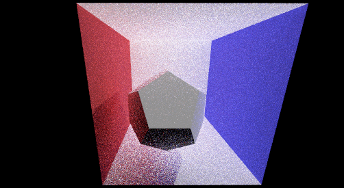
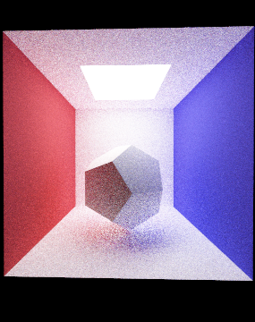
- Return the radiance calculated at the hit position. My implementation works fine for rendering triangles but has trouble rendering spheres. AS seen in figure, even after 512 samples, spheres are not rendered in the image. Whereas, models with triangle primitives are rendered just fine. Plus, the current code works fine for area lights and point lights. I have included results from using both point lights and area lights
I followed this up with the Ray Tracing in One Weekend series to fill up void in my basic knowledge. You can follow it here : Ray Tracing in One Weekend